What is UML ?
It is the general-purpose modeling language used to visualize the system. It is a graphical language that is standard to the software industry for specifying, visualizing, constructing, and documenting the artifacts of the software systems, as well as for business modeling.
Benefits of UML:
- Simplifies complex software design, can also implement OOPs like a concept that is widely used.
- It reduces thousands of words of explanation in a few graphical diagrams that may reduce time consumption to understand.
- It makes communication more clear and more real.
- It helps to acquire the entire system in a view.
- It becomes very much easy for the software programmer to implement the actual demand once they have a clear picture of the problem.
Types of UML: The UML diagrams are divided into two parts: Structural UML diagrams and Behavioral UML diagrams which are listed below:
- Structural UML diagrams
- Class diagram
- Package diagram
- Object diagram
- Component diagram
- Composite structure diagram
- Deployment diagram
- Behavioral UML diagrams
- Activity diagram
- Sequence diagram
- Use case diagram
- State diagram
- Communication diagram
- Interaction overview diagram
- Timing diagram
UML class diagrams: Class diagrams are the main building blocks of every object-oriented method. The class diagram can be used to show the classes, relationships, interface, association, and collaboration. UML is standardized in class diagrams. Since classes are the building block of an application that is based on OOPs, so as the class diagram has an appropriate structure to represent the classes, inheritance, relationships, and everything that OOPs have in their context. It describes various kinds of objects and the static relationship between them.
The main purpose to use class diagrams are:
- This is the only UML that can appropriately depict various aspects of the OOPs concept.
- Proper design and analysis of applications can be faster and efficient.
- It is the base for deployment and component diagram.
There are several software available that can be used online and offline to draw these diagrams Like Edraw max, lucid chart, etc. There are several points to be kept in focus while drawing the class diagram. These can be said as its syntax:
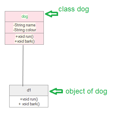
- Each class is represented by a rectangle having a subdivision of three compartments name, attributes, and operation.
- There are three types of modifiers that are used to decide the visibility of attributes and operations.
- + is used for public visibility(for everyone)
- # is used for protected visibility (for friend and derived)
- – is used for private visibility (for only me)
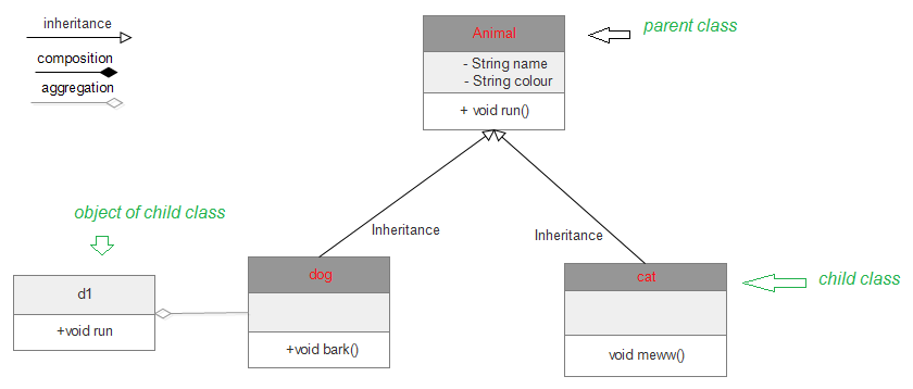
Below is the example of Animal class (parent) having two child class as dog and cat both have object d1, c1 inheriting properties of the parent class.
Where to Use Class Diagrams?
The class diagram is also considered as the foundation for component and deployment diagrams. Class diagrams are not only used to visualize the static view of the system but are also used to construct the executable code for forward and reverse engineering of any system.
The class diagram clearly shows the mapping with object-oriented languages such as Java, C++, etc. From practical experience, a class diagram is generally used for construction purpose.
In a nutshell, it can be said, class diagrams are used for −
- Describing the static view of the system.
- Showing the collaboration among the elements of the static view.
- Describing the functionalities performed by the system.
- Construction of software applications using object-oriented languages.
Java
import java.io.*;
class GFG {
public static void main(String[] args)
{
dog d1 = new dog();
d1.bark();
d1.run();
cat c1 = new cat();
c1.meww();
}
}
class Animal {
public void run()
{
String name;
String colour;
System.out.println( "animal is running" );
}
}
class dog extends Animal {
public void bark()
{
System.out.println( "wooh!wooh! dog is barking" );
}
public void run()
{
System.out.println( "dog is running" );
}
}
class cat extends Animal {
public void meww()
{
System.out.println( "meww! meww!" );
}
}
The process to design class diagram: In Edraw max (or any other platform where class diagrams can be drawn) follow the steps:
- Open a blank document in the class diagram section.
- From the library select the class diagram and click on create option.
- Prepare the model of the class on the opened template page.
- After editing according to requirement save it.
There are several diagram components that can be efficiently used while making/editing the model. These are as follows:
- Class { name, attribute, method}
- Objects
- Interface
- Relationships {inheritance, association, generalization}
- Associations {bidirectional, unidirectional}
Class diagrams are one of the most widely used diagrams in the fields of software engineering as well as business modeling.
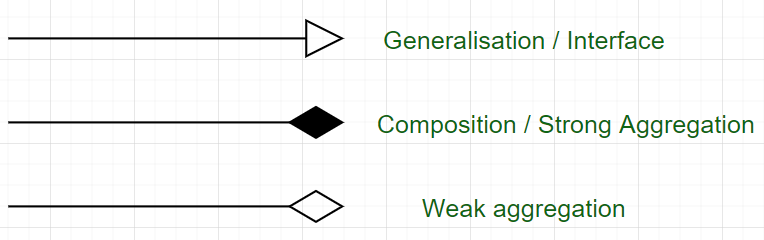
The exact meaning of the arrows :
Source: https://www.geeksforgeeks.org/unified-modeling-language-uml-class-diagrams/
Posted by: tonettetonettenewfielde0272267.blogspot.com

Post a Comment